
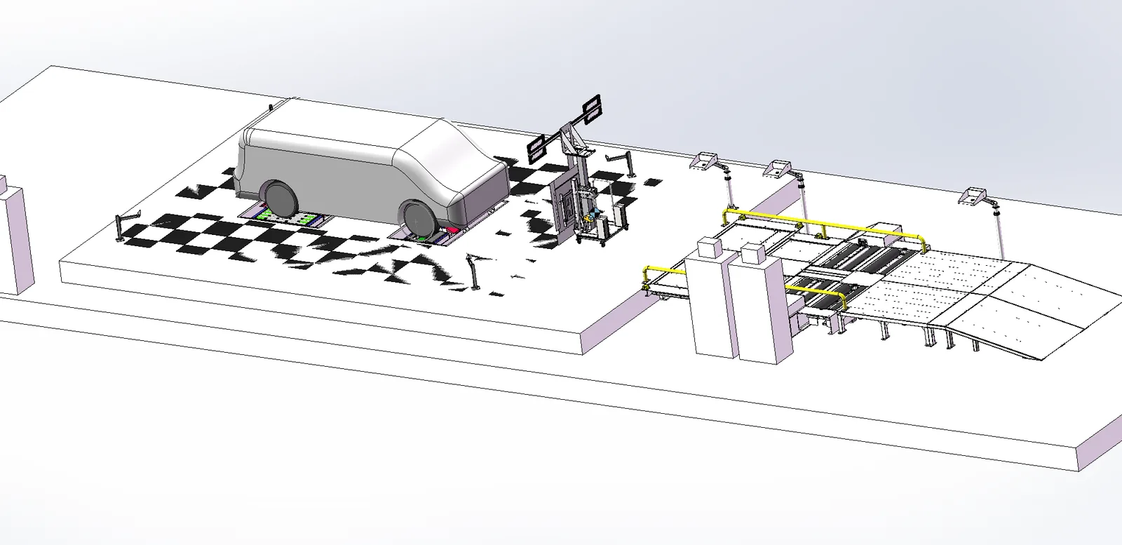
Simplified ADAS Calibration Equipment
Adas Calibration EquipmentCalibration equipment for LDW cameras, AEBS/FCW front radar (reflector type), BSD corner radar and AVM surround-view cameras. LDW height 1500-1700mm, AEBS height 500-800mm, worm-turbine-gear-rack two-stage synchronous lift, wheeled target trolley with locating pins, wireless Bluetooth OBD module and calibration/flashing software.
Product Details
Simple ADAS calibration equipment
LDW camera + AEBS/FCW radar + BSD angle radar + AVM surround view calibration · Mobile target trolley with positioning pin · Adjustable target height
Simple ADAS calibration station general layout (vehicle, calibration frame, target area and computer cabinet)
One machine covers four types of calibration
The same set of equipment can complete the calibration of LDW lane deviation warning camera, AEBS/FCW forward radar (in the form of reflector), BSD angle radar and AVM 360 surround camera, adapting to different vehicle heights.
Mobile Targeting Trolley
LDW and radar target trolleys use wheeled movement with positioning pins, which can be reset when pushed to the position of the positioning pins measured during installation. The target height is synchronously adjusted through two stages: worm - turbine - gear - rack.
Easy Economy · Low Beat Friendly
Simplified structure and low input, suitable for automobile manufacturers' overseas factories or low-beat ADAS calibration stations; equipped with wireless Bluetooth OBD module and calibration/brushing software, no need to drag cables.
产品概述
ADAS Advanced Driver Assistance System uses a variety of sensors installed on the vehicle to collect environmental data inside and outside the vehicle at the first time, and perform technical processing such as static and dynamic object identification, detection and tracking, so that the driver can detect possible hazards in the fastest time. It is an active safety technology to improve safety.The sensors used in ADAS are mainly cameras, radars, lasers and ultrasound, which can detect light, heat, pressure or other variables used to monitor the state of the car, usually located in the front and rear bumpers of the vehicle, side mirrors, inside the driving rod or on the windshield.
The camera needs to be calibrated after installation. The role of calibration is to confirm the spatial position of the camera and correct the distortion. The radar also needs to be calibrated after installation to calibrate the spatial position.
Simple ADAS calibration equipment provides a standardized calibration environment for LDW and radar calibration: it ensures that the LDW pattern coincides with the center of the calibration metal plate and the center of the car, and provides an accurate distance between the target and the car. The equipment structure is simple and easy to operate, suitable for automobile manufacturers overseas factories or low-beat ADAS calibration station applications.
Core Strengths
- It can meet the calibration of two intelligent assisted driving systems, LDW and AEBS (reflector form), and can adapt to different vehicle heights.
- LDW calibration height adjustment range 1500mm ~ 1700mm (the center of the calibration plate is from the ground, according to the actual model).
- The AEBS calibration height adjustment range is 500mm ~ 800mm (the center of the pyramid is from the ground, according to the actual model).
- It adopts worm-turbine-gear-racket gear transmission, simple adjustment method, convenient and reliable use process.
- The use of two-stage synchronous lifting transmission mode can not only achieve easy operation and observation at the lowest height, but also achieve the calibration of higher positions.
- The LDW calibration plate of the calibration frame can be fine-tuned by adjusting the worm, and two horizontal bubbles are installed above the fine-tuning mechanism to further ensure the accurate position of the calibration plate.
- The target trolley adopts wheeled movement with positioning pins, and the calibration rack can be pushed to the position of the positioning pins measured during installation, which is convenient for repeated positioning.
- The vehicle aligner determines the position of the vehicle's front axle and the vehicle's center, providing a unified reference for calibration.
- The wireless Bluetooth OBD module is connected to the vehicle OBD interface, communicates with the wireless receiver in the computer cabinet, and does not need to drag the cable during the calibration process.
- The computer cabinet stores industrial computers and wireless receivers, and the calibration software runs on the industrial computer for calibration; the cabinet can be simplified into a tablet computer.
- The LCD TV is used to display the calibration process and results; the driver platform is used to store barcode scanners, printers.
- The calibration software has both a flashing function and supports ADAS firmware file flashing and radar, camera, BSD and other calibration functions.
Equipment composition
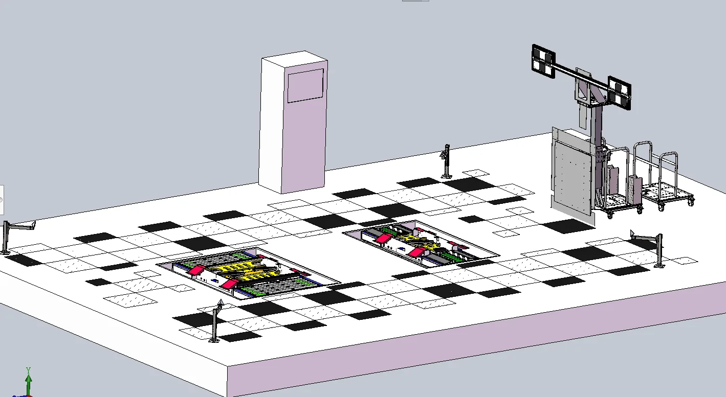
Calibration area layout: vehicle aligner, LDW/radar target trolley, corner radar and AVM ground pattern
- Computer cabinet:Used for storing industrial computers and wireless receivers, and running calibration software on industrial computers for calibration.
- LDW Target:Camera used to calibrate the car.
- Radar targets:Radar used to calibrate the car.
- Mobile trolley:Used for moving camera targets and radar targets, wheeled movement, with positioning pins.
- Vehicle aligners:It is used to determine the position of the front axle and the center of the vehicle, and provides two reference reference lines between the center of the front axle and the center of the vehicle.
- Driver Platform:For storing barcode scanners, printers.
- Liquid crystal displayUsed to display the calibration process and results.
- Corner radarUsed to calibrate BSD blind spot monitoring of automobiles.
- Ground AVM pattern:Used to calibrate the 360 surround camera of the car (painted on the ground by the customer as directed by our company).
Configuration Checklist
| No. | Name | Specification/model | Quantity | Remarks |
|---|---|---|---|---|
| 1 | LDW and Radar Target Trolley | TYX-JY2000 | 1 lot | LDW pattern + radar target, wheeled movement with positioning pin |
| 2 | Angular radar or reflector | TYX-RD2001 | 2 套 | BSD 盲区监测标定 |
| 3 | 汽车对中台(车辆摆正器) | ALIGNER-2000 | 1 lot | 确定车辆前轴和中心位置 |
| 4 | 计算机柜 | TS8 | 1 lot | 存放工控机与无线接收器,可简化为平板电脑 |
| 5 | 无线 OBD 模块 | OBD | 2 套 | 无线蓝牙,与车辆 OBD 接口连接 |
| 6 | 标定及刷写软件 | JT-SW2000 | 1 lot | 支持 ADAS 固件刷写与雷达、摄像头、BSD 标定 |
| 7 | 工业计算机及显示器 | IPC-610L | 1 lot | 研华工控机 |
| 8 | 标签打印机 | 惠普 | 1 台 | — |
| 9 | 条码扫描枪 | 斑马 LI4278 | 1 把 | 扫描 VIN 码 |
| 10 | AVM 标靶(地面刷漆) | — | — | 我公司指导,由客户安排地面刷漆 |
注:以上为标定设备及软件的标准配置;安装调试、包装与运输等按商务约定执行。实际配置以双方签订的技术协议为准。
机械结构
简易 ADAS 标定架可以满足车辆的 LDW、AEBS(反射板形式)两种智能辅助驾驶系统的标定,同时能够适应不同的车辆高度。
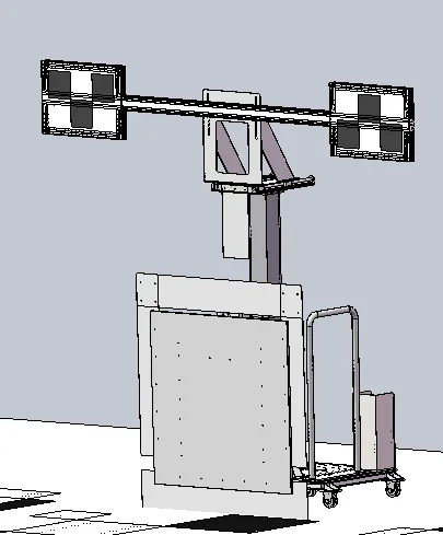
图 1 简易 ADAS 标定架(LDW 标定板 + 雷达标靶,轮式移动)
主要技术指标
| No. | 内容 | 技术参数 |
|---|---|---|
| 1 | LDW 标定高度调节范围(标定板中心距地面) | 1500mm~1700mm(根据实际车型定) |
| 2 | AEBS 标定高度调节范围(角锥中心距地面) | 500mm~800mm(根据实际车型定) |
| 3 | 传动方式 | 齿轮传动:该机构使用蜗杆-涡轮-齿轮-齿条作为传动方式,调节方式简单,使用过程方便、可靠 |
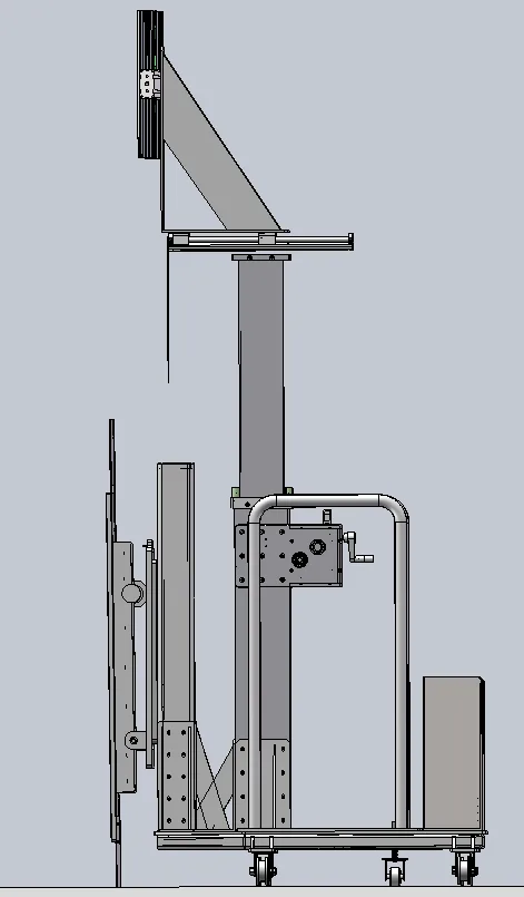
图 2 传动方式(蜗杆-涡轮-齿轮-齿条,两级同步升降)
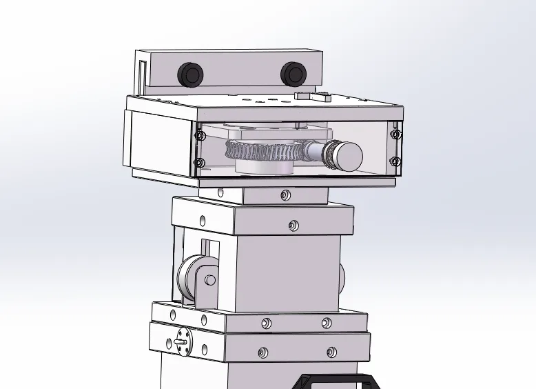
图 3 LDW 标定板的角度调节(蜗杆微调 + 水平泡)
该机构在操作方便、快捷的前提下,选用了两级同步升降传动方式,既可实现最低高度时操作观察方便,又可实现较高位置的标定。标定架 LDW 标定板可通过调节蜗杆实现角度微调,并在微调机构的上方安装两个水平泡,可进一步保证标定板位置的准确。
标定原理
简易标定设备提供 LDW 与雷达的标定环境,保证 LDW 图案与标定金属板的中心与汽车中心重合,并提供准确的标靶到汽车间的距离。
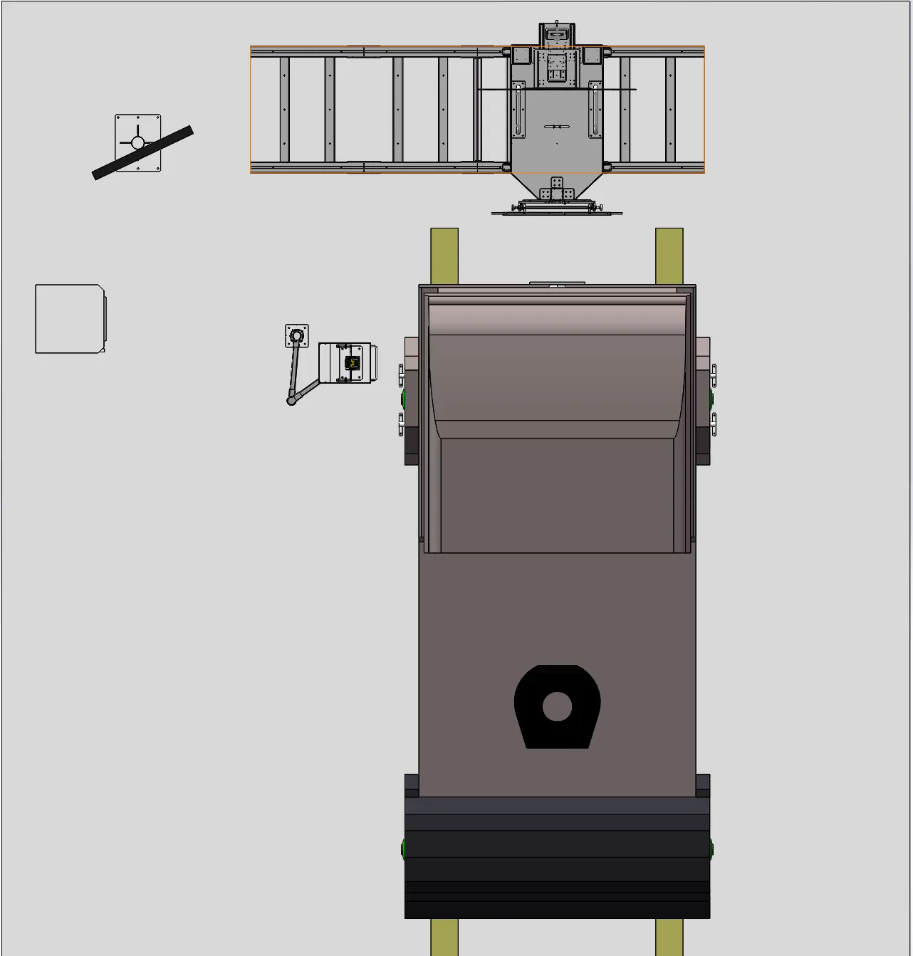
图 4 标定基准:车辆中心、前轴中心与标靶定位关系
- 通过前轴限位表(车辆摆正器)确定前轴中心距离。
- 通过前悬长度确定摄像头与雷达到标靶的距离。
- 将标定架推到汽车中间位置,至安装时测量的定位销位置。
标定工艺流程
① 车辆驶入位置 将车辆驶入到摆正器,前轴到位;将标定架推到汽车中间位置,至安装时测量的定位销位置。
② 扫描 VIN 码 扫描车辆 VIN 码,由软件自动识别车型与标定程序。
③ 插入 OBD 模块 将无线蓝牙 OBD 模块插入汽车的 OBD 接口,与计算机柜内的无线接收器建立通信。
④ LDW 标定 打开标定软件选择 ADAS 标定软件,进入对应车型的摄像头标定页面,完成连接、安全认证、写入参数与标定。
⑤ 雷达标定 进入雷达标定页面,完成连接、标定与结果确认。
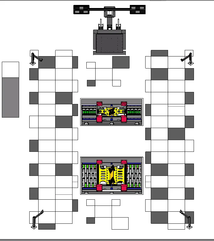
图 5 车辆驶入摆正器,前轴到位
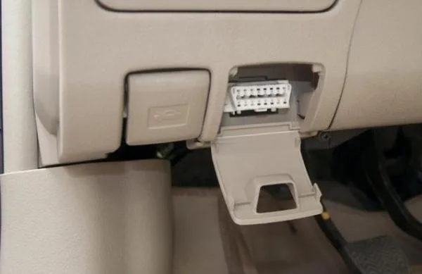
图 6 车辆 OBD 接口
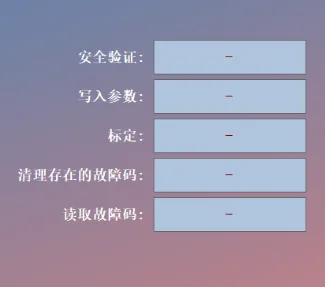
图 7 标定软件状态:安全验证 / 写入参数 / 标定 / 读取故障码
标定软件功能说明
- 刷写功能:支持 ADAS 固件文件刷写。
- 标定功能:支持雷达、摄像头、BSD 等标定功能。
- 连接 / 断开:连接或断开无线蓝牙 OBD 模块。
- 安全认证:开始标定前,程序与 ECU 建立通信后需要进行安全认证,认证通过后才可进行标定。
- 写入参数:写入与 LDW 相关参数到 ECU 控制器里面。
- 标定:准备好标定板环境后按下该按钮开始标定,并显示标定结果,标定成功提示「OK」,标定失败提示「NOK」。
- 清除故障码 / 读取故障码:清除或读取车辆故障码。
注意:雷达标定时,车的左前方、右前方与正前方需保持空旷状态,不可有其它物体,否则极大概率会标定失败。
无线蓝牙 OBD / VCI 模块
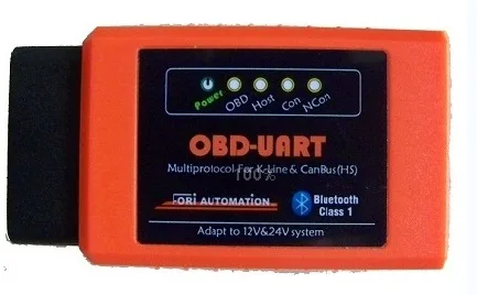
无线蓝牙 OBD 模块(LED 指示灯:Power / OBD / Host / Con / NCon)
- Power:模块电源指示灯。
- OBD:OBD 通信灯。
- Host:与计算机通信灯。
- Con:与蓝牙连接指示灯。
- NCon:蓝牙断开指示灯。
OBD 模块使用 12 伏或 24 伏车辆电源(9~30V),上电后与计算机(或平板电脑)通过无线蓝牙进行通信,完成上位机程序与车辆的数据交互。
| Item | 描述 |
|---|---|
| 通信 | 蓝牙 2.1 |
| 无线接收频率 | 无线 BT V2.1,2.4 GHz |
| Input voltage | 12 VDC 至 24 VDC |
| 电源电流 | 170 mA @ 12 VDC;100 mA @ 24 VDC |
| Operating Temperature | 0℃ 至 60℃(环境) |
| Storage Temperature | -65℃ 至 100℃(环境) |
| 尺寸(长×宽×高) | 149mm(5.87") × 86mm(3.38") × 35mm(1.28") |
| Weight | 290 g (0.64 lb.) |
无线 ECU 模块(其它)
蓝牙诊断盒采用美国进口的蓝牙 ABS 解码器模块,具备 A 类蓝牙标准,传输距离可达 100m。通过 DB9 口与车辆 OBD 接口连接,支持 ISO9141 与 OBD 电缆连接。
- A 类蓝牙,距离高达 100 米 / 330 英尺范围内;波特率从 9600 到 2M 波特,提高数据吞吐量,提供更快的数据采集点。
- 支持所有 OBD 协议法规:ISO15765-4(CAN)、ISO14230-4(关键字协议 2000)、ISO9141-2(亚洲、欧洲、克莱斯勒汽车)、J1850 VPW(通用汽车)、J1850 PWM(福特汽车)等。
- 大内存缓冲区允许扫描工具接收大量的数据;提供稳定的 ISO 和 KWP 连接。
工业计算机
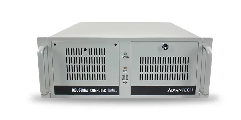
研华 IPC-610L 工业计算机
- 型号:研华 IPC-610L。
- 配置:IPC 610L,250W,EBC-GF81,i7-4790,8G×2,1T 机械×2,研华键鼠,主板支持 VGA+HDMI 输出,双网口,6 个串口全引出。
- 主板型号:EBC-GF81。
配件:OBD 延长线
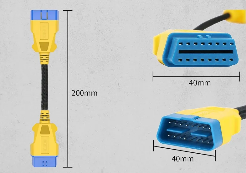
OBD2 延长线(长度 200mm,接口宽 40mm)
VCI 设备可通过测试主线连接车辆 OBD II 并获得供电,主电缆将 OBD 模块连接到车辆的数据链路连接器(DLC)。
| Item | 规格 |
|---|---|
| 产品名称 | OBD2 延长线 |
| 长度 | 200mm |
| Weight | 105g |
| 材质 | 尼龙 PVC |
| 直径 | 10.00mm |
| 适用车型 | 所有 OBD16 诊断接口汽车 |
典型应用
- 汽车整车厂总装车间 ADAS 标定工位(LDW、AEBS/FCW、BSD、AVM)。
- 汽车制造商海外工厂、低节拍或小批量混线生产场景。
- 售后维修站 ADAS 标定与 ADAS 固件刷写。
- 与车辆摆正器、条码扫描、标签打印组成完整的下线标定工位。
Contact us
北京泰元祥科技有限公司
电话:010-89780650 手机:18611929790(李永坡)
Email: liyongpo@taiyuanxiang.cn
Address: Room 3027, Building 1, Hongfu No. 10, Beiqijia Town, Changping District, Beijing
免责声明:本页技术参数、配置及图片均依据产品技术方案整理,仅用于产品介绍。因产品持续改进,实际供货以双方签订的技术协议与合同为准;本页所载参数不作为验收依据。
Related Products
View All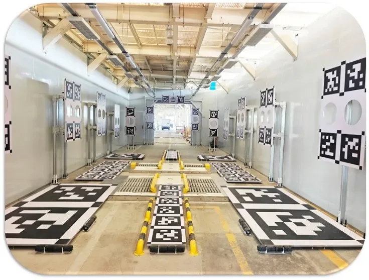
Autonomous Vehicle Calibration Room
Full-vehicle sensor calibration room with automated target workflow
Learn More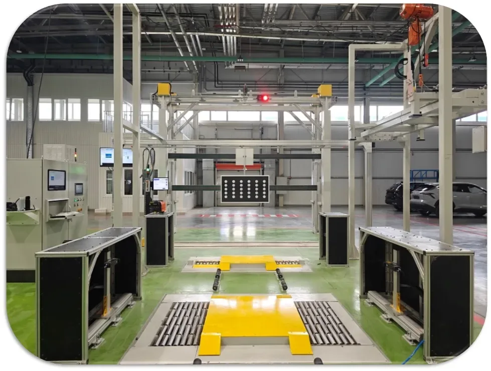
Wheel Arch Height Measuring Device
前轮眉高度测量传感器(2D相机) 传感器采用激光基于三角原理测量,传感器内的线性激光的位置及与相机的角度经过标定后参数被固定。635nm的红色激光垂直照射到前轴平面上轮眉最高处,经过2D相机在CCD内成像并被识别,软件对激光线解算出拐点,并根据激光三角形法原理求解拐点的Y和Z坐标,其中Z坐标也就是轮眉的高度
Learn More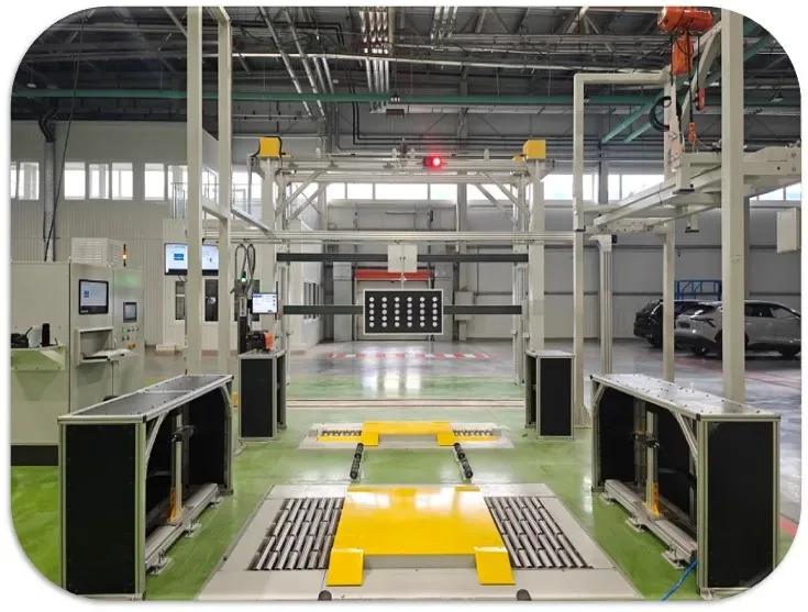
Integrated ADAS Station Calibration Frame
Aluminum integrated frame for zero-point verification
Learn More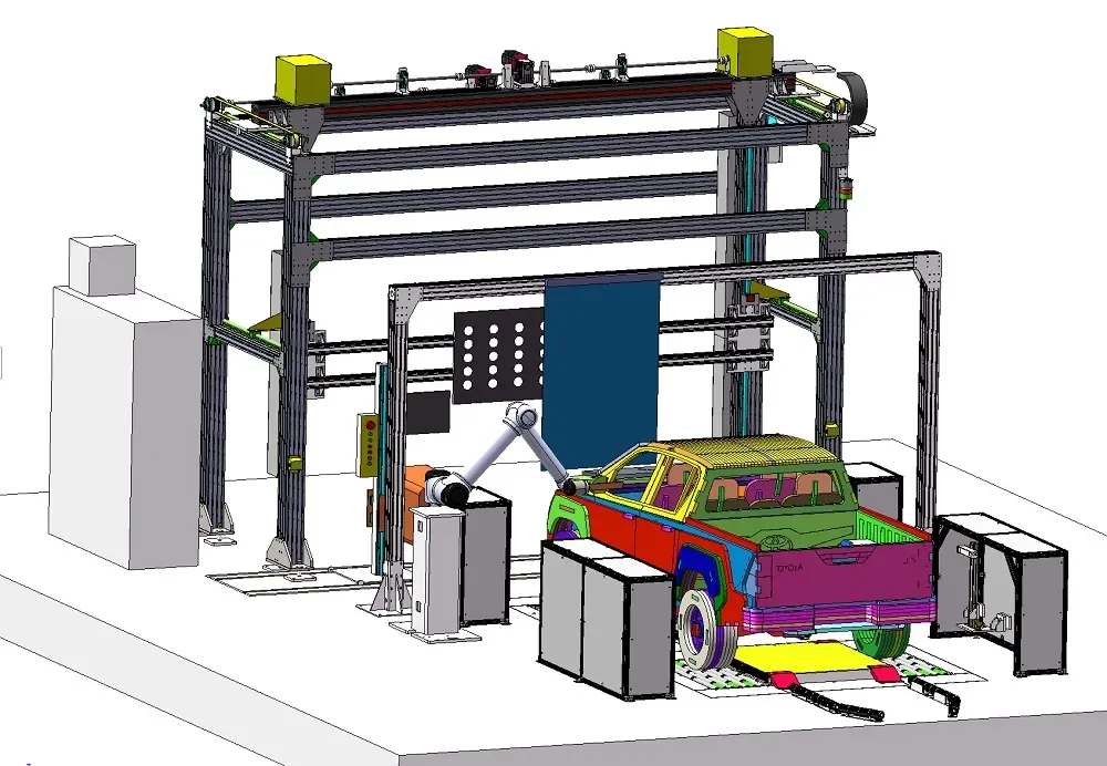
HUD Calibration & Inspection System (Collaborative Robot Type)
UR10 collaborative robot with SONY industrial camera simulates human-eye viewpoints; automatic curtain blocks ambient light; SICK area scanners and ultrasonic glass detection for safety; fully automatic calibration by PLC + IPC
Learn More